Drawing
Stroke
You can apply one or multiple strokes to a path using the Appearance panel. For a complete description of the panel's interface, refer to the Appearance Panel section.
To open or hide the Appearance panel, To open the panel, tap on the corresponding icon in the main window.
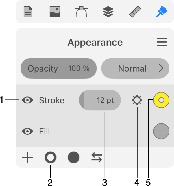
1 - Strokes are listed in the Appearance panel among other properties.
2 - Add stroke.
3 - Stroke width.
4 - Open stroke properties.
5 - Stroke color. Tapping on this button opens the Color panel.
The Opacity and Blend Mode parameters are the same as you can find in the Layers panel.
Add and Delete a Stroke
Before adding or deleting a stroke, you should select a path in your design.
To add a stroke, tap on the ring icon in the bottom bar of the Appearance panel.
To delete a stroke, select it in the Appearance panel. Then slide over its name to the left. Then tap on the trash bin icon.
It is possible to hide a stroke without actually removing it. To do this, use the respective eye icon in the Appearance panel.
Edit Stroke Width
The Path Width tool ![]() lets you customize the variable width of the Stroke. If the object has several Strokes, the tool will modify the upper Stroke. In order to edit a lower Stroke, drag it to the upper position in the Appearance panel. When the editing is finished, move the Stroke to the original position.
lets you customize the variable width of the Stroke. If the object has several Strokes, the tool will modify the upper Stroke. In order to edit a lower Stroke, drag it to the upper position in the Appearance panel. When the editing is finished, move the Stroke to the original position.
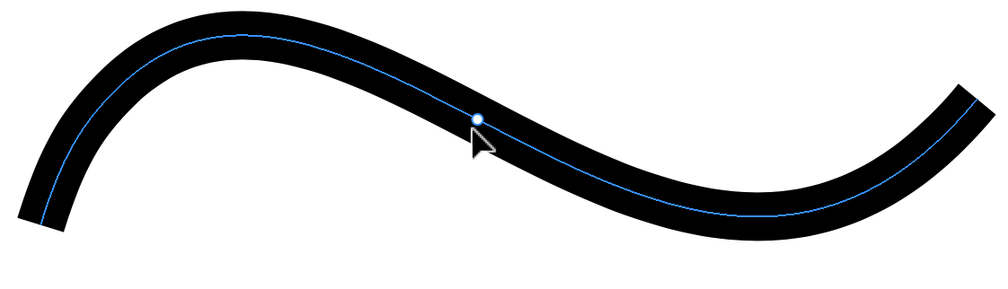
The path that you are going to edit must have a Stroke applied. If the most part of the stroke should have a certain width, let's say 20 px, you can set that width in the Appearance panel.
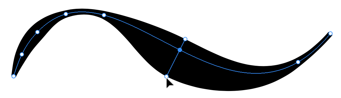
To modify the width, select a path, and then activate the Path Width tool. Press with your finger and hold at a point where the width should be changed.
Drag the finger off the path to set a new width at the selected point. This point will have three handles. If you drag the handle in the middle, the point that defines the width will move along the path. If you drag any of the handles on the sides, you will adjust the stroke width.
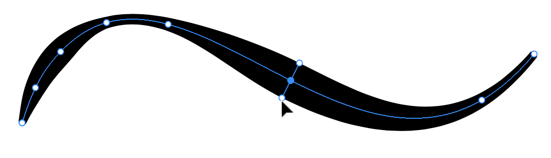
While holding down two fingers on free space, you can move a handle on only one side. This lets you create non-symmetrical strokes.
If you deactivate the tool, the handles will disappear until you activate the tool again.
The Path Width tool lets you manipulate only the stroke width handles. For other operations like selecting, moving or resizing objects, you should activate an appropriate tool.
Modifier Keys and Shortcut Summary
With an external keyboard, you can use the following shortcut and modifier keys.
Shortcut:
- W activates the Path Width tool.
Path Width tool modifier keys:
- Space switches to the Pan mode.
- Command switches to either Move or Selection tool depending on which of them was active most recently.
- Option lets you move a handle on one side keeping the position of the opposite handle unchanged. This makes the stroke asymmetrical in relation to the path.
Properties of a Stroke
The Appearance panel gives you direct access to the width and color of strokes. The Color panel is described in the Color Panel section. To access all available properties, tap on the gear icon.
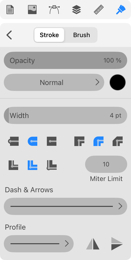
The Width parameter is the same as the width you can set in the Appearance panel.
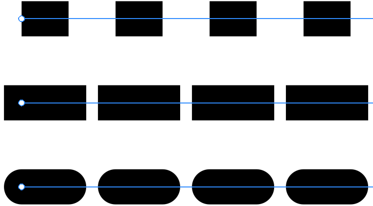
The Cap options ![]() define whether the stroke should end where the path ends, or it should go a half-width farther. In the second case, you can choose if the stroke should be rounded. The option applies to a solid line as well as to individual elements of dashed or dotted lines.
define whether the stroke should end where the path ends, or it should go a half-width farther. In the second case, you can choose if the stroke should be rounded. The option applies to a solid line as well as to individual elements of dashed or dotted lines.
The Corner options ![]() let you select how the stroke looks at corners. You can make it sharp, rounded or clipped.
let you select how the stroke looks at corners. You can make it sharp, rounded or clipped.
The Limit parameter lets you set up the miter limit. It defines how far a stroke can stretch out in sharp corners. The spike gets cut off depending on the angle and miter limit. This parameter has no effect with rounded or clipped corners, as well as when Align is set to the right option.
Let's compare corners with different angles and stroke widths at tree miter limit values.
We can see that the corner with smaller angle gets clipped at higher value of miter limit. The clipping does not depend on the stroke width.
The Align options ![]() let you align a stroke to the center of the path, or outside or inside of the shape. Notice that the alignment options can work only with closed paths.
let you align a stroke to the center of the path, or outside or inside of the shape. Notice that the alignment options can work only with closed paths.
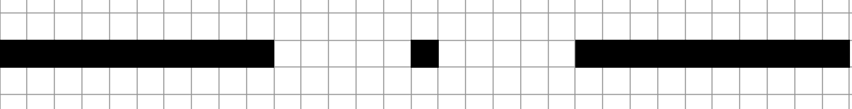
The following set of controls lets you create dashed and dotted lines.
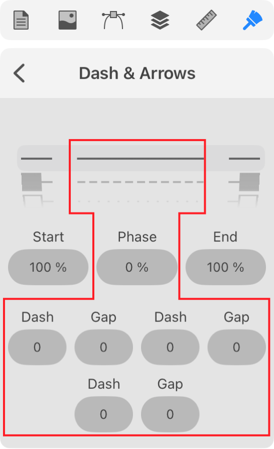
At the top, there are patterns that have different combinations of dots and dashes.
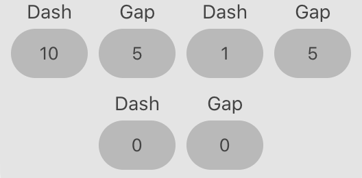
Any dashed line can be described as a sequence of dashes and gaps of a particular length. So, in order to create your own pattern, you can fill in the Dash and Gap fields at the top. For example, to create a pattern like "long dash - gap - dot - gap", you can type in 10 - 5 - 1 - 5 starting from the leftmost dash field.
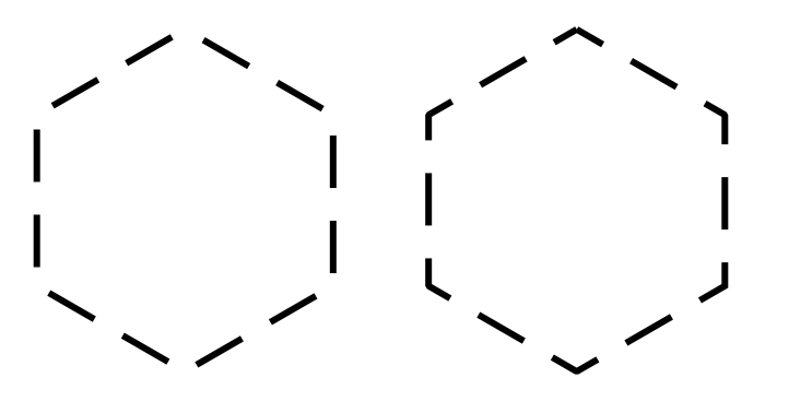
The Phase parameter moves the pattern along the path. With this slider, you can place dashes at corners of your shape or align the pattern to other features of the path.
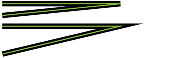
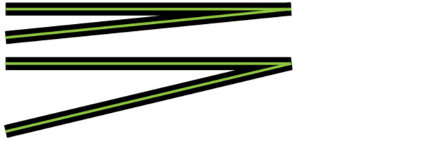
The two pairs of identical controls let you add arrowheads or other elements to a Stroke at the path ends.
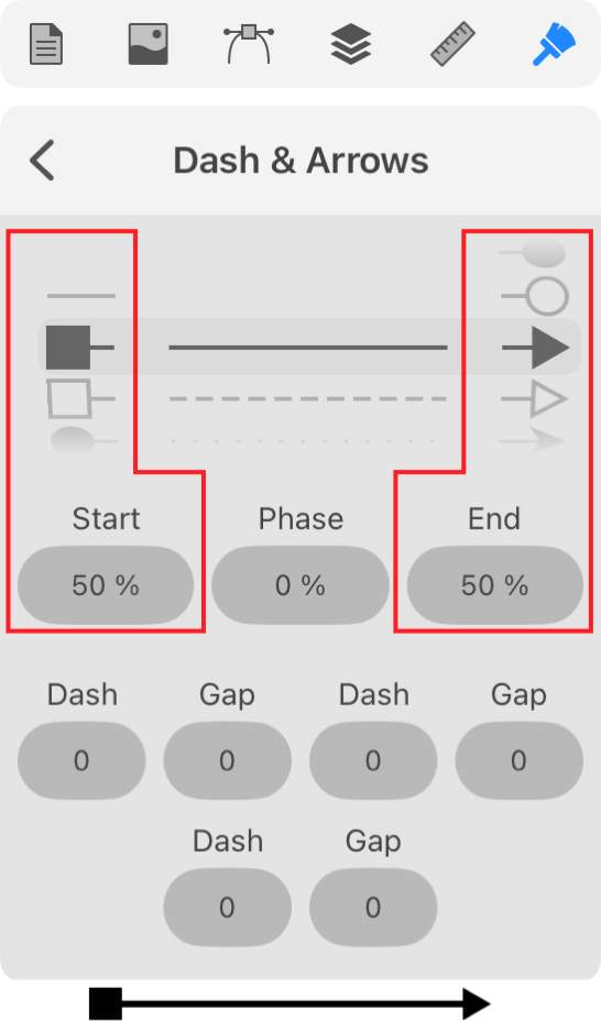
To add an arrowhead to a Stroke, choose a pattern from the drop-down menu. In order to adjust the arrowhead's size, change the numeric value below the drop-down menu. Arrowheads and dashed patterns are supported only with the Uniform profile. They will not be applied to the Stroke if you choose a variable-width profile.
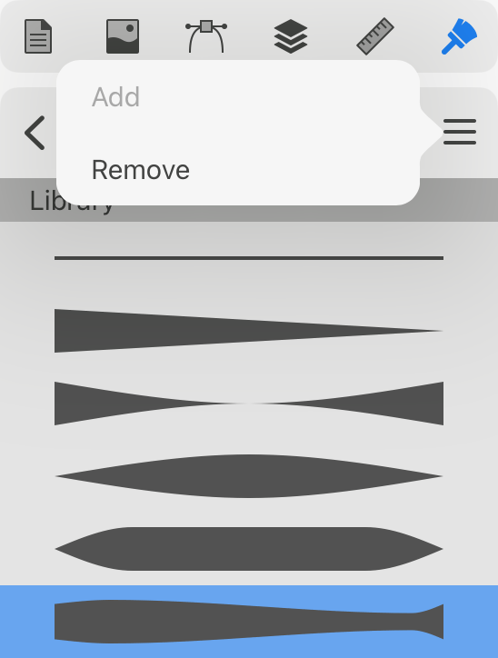
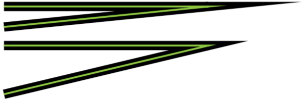
You can change the profile of a Stroke using the Profile button in the Appearance panel. It defines how the stroke width changes along the path.
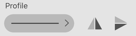
By default, strokes have the Uniform profile that creates lines with constant width. However, there are other options as well. For example, the stroke width can gradually change from max to min value along the path.
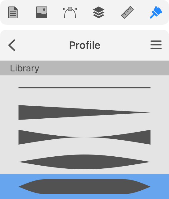
You can add your own profile to the list if you wish to reuse it. To do this, you create a new profile using the Path Width tool. Bring up the list of profiles. Tap on the menu icon to the right from the panel's title and choose Add. To delete a custom profile from the list, select this profile and tap on Remove in the menu.