Drawing
Path and its Features
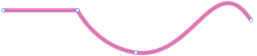
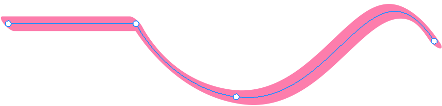
Drawing tools create objects that are based on paths. Although a line, brush stroke or geometrical figure may look very different, their shape is defined by a thin line called the path. The path itself is invisible on the canvas unless you select it. The object becomes visible thanks to an applied stroke, brush, fill or other properties.
You can see it only because it is selected
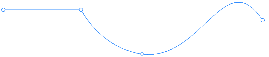
All paths are made up of anchor points and segments (lines that link points). So, the simplest path consists of one segment and two anchor points at its ends. A path is closed if its start and end points are the same point.
Paths are listed in the Layers panel as items named Path.
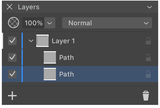
The color of a selected path on the canvas (don't confuse it with a stroke) coincides with the color of the layer the path belongs to. This color is indicated in the Layers panel as a vertical line to the right from the check boxes. The same color is used to display the selection frame.
Features of a Path
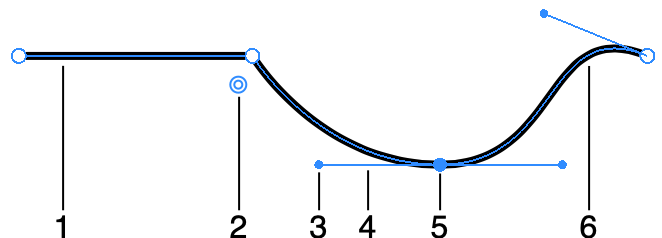
1 - Straight segment.
3 - Direction point. A direction point works as a handle to manipulate the respective direction line.
4 - Direction line.
5 - Anchor point.
6 - Curved segment.
Segments
Depending on the way you draw a segment, it can be straight or curved. You can change the shape of segments by editing the path.
Anchor Points
Anchor points define the shape of a path in two ways. Primarily, they are intermediate points for the path. So, by changing the location or amount of the intermediate points, you can significantly change the shape of the path.
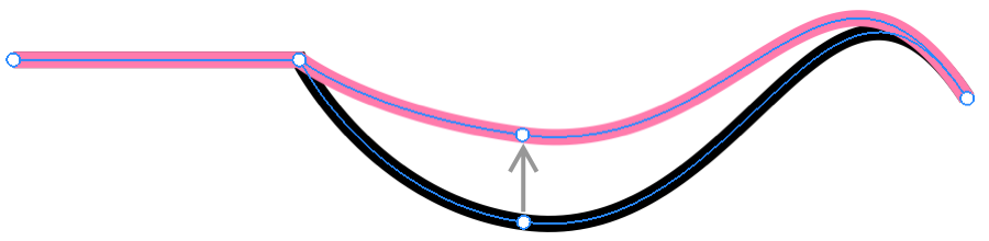
Also, anchor points can have direction lines that let you adjust the curvature of the corresponding segments. In this case, anchor points in the middle of the path have two direction lines because two segments are attached to this point. An end point has only one direction line.
Corner Points and Smooth Points
Any anchor point is either smooth or corner point. The Edit a Path section explains how to turn an anchor point from one type to another.
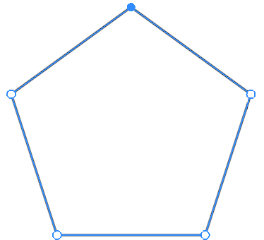
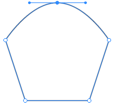
At a corner point, a path breaks, creating a corner. Corner points often have no direction lines. At a smooth point, the path creates no corner. This happens because the angle between the direction lines is 180 degrees. With any other angle, the segments will create a corner. The segments that are attached to the same corner point can be straight or curved in any combination.
A corner anchor point will not show direction lines by default even if you select it. The direction points of a corner point and the corner point itself have exactly the same location. Because of this, the direction lines have zero length and, consequently, are not visible.
The Change the Type of an Anchor Point subsection explains how to convert a smooth point to a corner point and vice versa.
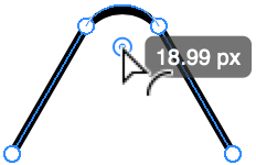
Rounding Corners
The app can display a handle near a corner point when the Selection tool is activated. This handle lets you change the radius of the rounded corner. Read the Rounding Corners section for more details.
Direction Lines and Direction Points
Direction lines let you change the direction and curvature of a segment. To operate a direction line, you should drag its direction point. You can adjust the angle and length of direction lines.
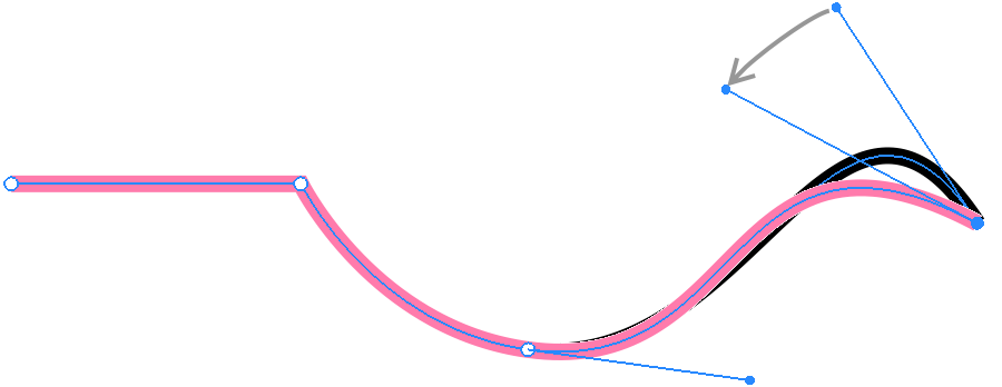
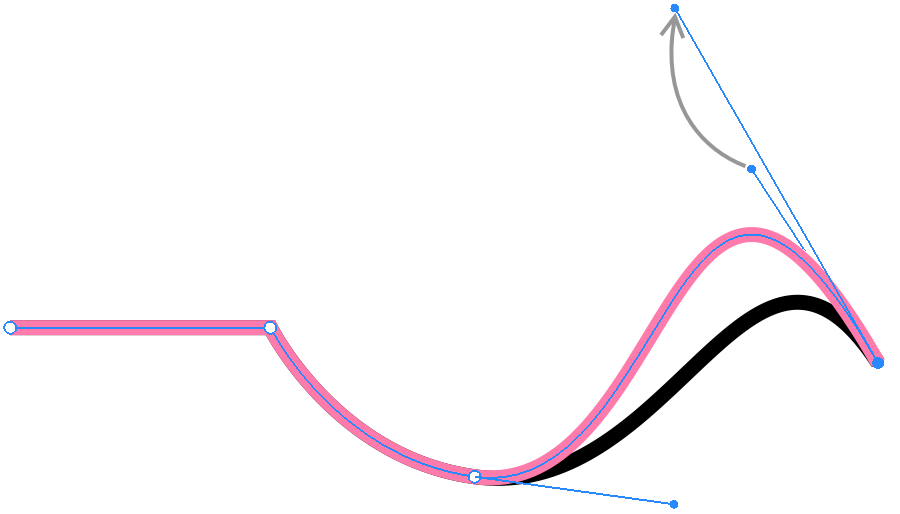
The Manipulate Direction Lines subsection explains how to work with direction lines.